
Blog
How to Test Circuit Breakers: A Practical Field Guide

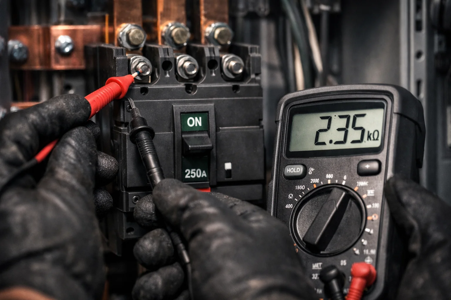
A circuit breaker spends almost its entire life doing nothing. It sits closed, carrying current, for years. Then one day a fault arrives and it has milliseconds to do the only job it was bought for.
That is the whole problem with breakers. There is no gradual warning, no performance drop-off you’d notice during normal operation. A breaker with a seized mechanism, a corroded contact, or a trip unit that drifted out of calibration looks exactly like a healthy one — right up to the moment it fails to clear a fault and the arc energy goes somewhere it shouldn’t.
Testing is the only way to know. This guide covers what to test, how, and what the numbers should look like.
Before Anything Else: Safety
This is not a boilerplate paragraph. Breaker testing is one of the higher-risk activities in electrical maintenance, because you’re working on equipment whose entire purpose is handling energy that kills.
- Only qualified personnel. Not “experienced” — qualified, in the formal sense, with training in the specific equipment and the hazards. NFPA 70E and the equivalent local requirements exist for a reason.
- Full lockout/tagout, verified. Isolate, lock, tag, then test for absence of voltage with an instrument you have proven works before and after — test the tester on a known live source.
- On draw-out breakers, rack the breaker fully out to the disconnected or test position. On fixed breakers, isolate upstream and prove dead at the terminals.
- Ground everything, including capacitance. Long cables and large machines hold a charge. Apply safety grounds after proving dead.
- Discharge after every insulation or hi-pot test — DC test voltages leave a stored charge that will absolutely reach out and bite you, sometimes minutes later.
- Watch the stored energy in the mechanism. A charged closing spring on an ACB or VCB is a mechanical hazard entirely separate from the electrical one. Discharge the springs (close, then trip) before working on the mechanism. Keep hands clear of the linkage during any operation test.
- Arc flash PPE for anything done energized. Some tests — thermography, partial discharge surveys, some secondary injection work — happen with the equipment live. Do the arc flash risk assessment and wear the rated PPE, or don’t do the test.
If any of that reads as unfamiliar, this article is background reading, not a work instruction. Bring in a qualified testing organisation.
Know What You’re Testing
The test regime changes with the breaker type. Broadly:
- MCBs (miniature circuit breakers) — up to 125 A, DIN-rail, sealed. Not field-adjustable and usually not economically repairable. Testing is limited: visual condition, operation, and occasionally a primary injection check on the thermal-magnetic characteristic if you suspect nuisance tripping. Most of the time you replace rather than test.
- MCCBs (moulded case circuit breakers) — roughly 16 A to 1,600 A. Thermal-magnetic or electronic trip units. Testable and worth testing, particularly the trip unit.
- ACBs / air circuit breakers (LV power breakers) — typically 630 A to 6,300 A, draw-out, electronic trip units, full complement of accessories. These get the full treatment: mechanical, contact resistance, insulation, trip unit calibration, timing.
- MV/HV breakers — vacuum and SF₆ — 3.3 kV to 400 kV and beyond. Everything above, plus interrupter-specific tests: vacuum integrity, SF₆ gas quality, dynamic timing and travel analysis, and dielectric withstand at meaningful voltages.
The standards that govern this: IEC 60947-2 for LV breakers, IEC 62271-100 for HV/MV switchgear, and on the field-testing side ANSI/NETA ATS-2025 for acceptance testing of new equipment and ANSI/NETA MTS-2023 for maintenance testing of equipment in service. NETA also publishes ECS-2024 for commissioning and ETT for technician qualification. The NETA documents are the practical ones — they specify the actual field tests, procedures and acceptable values, and most consultants and clients in the region will accept a report written against them.
Test 1: Visual and Mechanical Inspection
Free, fast, and it finds more problems than any single electrical test. Do it first, every time.
- Look for discoloration and heat damage on terminals and busbar connections — a brown or blued connection is a story about resistance.
- Check for arcing marks, carbon tracking across insulating surfaces, cracked or crazed insulation, and moisture ingress.
- Check the arc chutes for erosion and splatter, and confirm they’re properly seated.
- On draw-out breakers, verify the racking mechanism moves freely through all positions, the primary and secondary disconnects engage properly and show no signs of overheating, and every interlock works. Shutters should close when the breaker is withdrawn. Try to defeat the interlocks in the ways an operator might do accidentally — that’s what they’re there for.
- Check bolted connection torque against the manufacturer’s values, using a calibrated torque wrench. In this region, and particularly on outdoor or unconditioned installations, thermal cycling between a 50°C afternoon and an air-conditioned night works joints loose over time.
- Also check the mechanism lubrication. Old grease that has hardened is one of the most common causes of slow or failed mechanical operation, and hot, dusty environments accelerate it — dust bonds into the grease and turns a lubricant into an abrasive paste.
Then operate the breaker manually several times. It should feel positive and consistent. Hesitation, grinding or variation between operations means the mechanism needs attention before you go any further.
Test 2: Contact Resistance (Micro-ohm / DLRO)
What it tells you: the condition of the main contacts and the current path through the breaker.
How: a micro-ohmmeter (ductor / DLRO) injects a DC test current — typically 100 A, and NETA specifies a minimum of 100 A for this test — through each pole from terminal to terminal, and measures the millivolt drop to derive resistance in microhms. Test each pole individually, with the breaker closed and fully isolated.
Why the high current matters: a low-current ohmmeter can read through a thin oxide film that a real fault current would have to punch through. The high test current gives you a measurement representative of actual service conditions.
Interpreting results: compare against three things, in order of usefulness — the manufacturer’s stated value, the readings from the other poles of the same breaker, and the historical trend for that breaker. NETA’s guidance is to investigate when readings deviate substantially from adjacent poles or from similar breakers; a commonly cited threshold is a deviation greater than 50% from the lowest value.
Typical values run from a few tens of microhms on small LV breakers to a few hundred on larger MV units, but the absolute number matters far less than the comparison. One pole at 180 μΩ when the other two read 45 μΩ tells you exactly where to look, no matter what the catalogue says.
Rising resistance means contact erosion, contamination, loose connections, or misalignment. It also means heat — power dissipation goes as I²R, so a contact resistance that has tripled is dissipating three times the heat at the same load, which accelerates the degradation that caused it.
Test 3: Insulation Resistance
What it tells you: the condition of the insulation system, and whether moisture or contamination has crept in.
How: an insulation resistance tester (megohmmeter) applies a DC voltage — commonly 500 V or 1,000 V for LV equipment, 2,500 V or 5,000 V for MV — and measures leakage current to derive resistance.
Test in both configurations:
- Breaker closed: pole-to-pole and pole-to-ground. This tests the bushing and support insulation.
- Breaker open: across the open contacts of each pole. This tests the interrupter’s ability to hold off voltage in the open position.
Interpreting results: as with contact resistance, trend beats absolute value. A reading that has fallen from 20 GΩ to 800 MΩ over three annual tests is telling you something important even though 800 MΩ still looks like a comfortable number.
Two corrections matter here and are routinely skipped in the Gulf, to the detriment of the data:
- Temperature. Insulation resistance roughly halves for every 10°C rise. A reading taken in a 45°C switchroom is not comparable to one taken at 20°C during the previous year’s cooler-season shutdown. Correct to a standard reference temperature — usually 20°C or 40°C — or your trend data is noise.
- Humidity. Surface moisture on bushings and insulators drags readings down and produces false alarms. Coastal sites in the UAE and the Eastern Province see this constantly. Use the guard terminal to exclude surface leakage where the test set supports it, and record ambient conditions on the report.
For better diagnostics on larger equipment, run a polarisation index (the ratio of the 10-minute reading to the 1-minute reading) or a dielectric absorption ratio (60 s to 30 s). A PI below about 1.0–1.5 on equipment that should show more suggests moisture or contamination even when the spot reading looks acceptable. Note that on very modern, very dry insulation systems with extremely high resistance, PI can be misleading — IEEE 43 discusses when to disregard it.
Test 4: Dielectric Withstand (Hi-Pot)
What it tells you: whether the insulation can actually withstand overvoltage, which is a different question from whether its leakage is low.
How: apply an elevated voltage — AC or DC depending on equipment and standard — for a defined duration, typically one minute, and confirm no breakdown or excessive leakage current.
This test is stress-inducing by design, and that is a real consideration. Applied carelessly, especially on aged insulation, it can turn a weakness into a failure on the test bench. That is arguably a good outcome (better in a shutdown than in service) but only if you intended it and have a spare.
Use manufacturer-specified voltages, not maximum values. Acceptance testing on new equipment typically uses higher voltages than maintenance testing on in-service equipment — NETA reflects this with reduced maintenance test values, commonly a percentage of the original factory test voltage.
For vacuum breakers specifically, the across-open-contacts hi-pot is the standard vacuum integrity check. A vacuum interrupter that has lost its vacuum will still pass a contact resistance test and still operate mechanically — nothing looks wrong — but it will fail catastrophically when asked to interrupt a fault. The dielectric test across the open gap is what catches it. This is not optional on vacuum switchgear.
Watch also for X-ray emission at elevated test voltages on vacuum bottles and maintain the manufacturer’s stated clearance. Always discharge and ground thoroughly after DC testing.
Test 5: Timing and Travel Analysis (MV/HV)
What it tells you: how fast the breaker actually operates, and whether the mechanism is degrading.
How: a circuit breaker analyser measures the time from trip or close command to contact separation or touch, for each pole independently, and — with a transducer fitted to the mechanism — records the full travel curve: stroke, velocity, overtravel, rebound and damping.
What good looks like: opening times in the range of tens of milliseconds, typically around 3 to 5 cycles for MV breakers depending on design, with pole-to-pole scatter within a few milliseconds. The manufacturer specifies the numbers; the analyser tells you whether you’re meeting them.
What the travel curve reveals that nothing else does: contact velocity is what determines whether the arc is stretched and cooled fast enough to interrupt. A mechanism with hardened grease, a weakening spring or a worn damper may still open, and still open within a tolerance you’d call acceptable on a simple timing test, but do it slowly enough that arc interruption is compromised. The velocity curve shows this directly.
In hot, dusty Gulf installations where grease degradation is accelerated, this is the test that catches the problem while it’s still a maintenance item.
Also run first-trip testing where practical — measuring the very first operation after a long period of sitting closed, before any exercise operations have freed things up. The first trip is the one that matters in a real fault, and it’s the one where a stiff mechanism shows itself. Once you’ve operated the breaker a few times for testing, you’ve lubricated away the evidence.
Test 6: Coil and Mechanism Checks
Measure trip coil and close coil resistance and compare to nameplate and to previous readings — a change indicates shorted turns or a developing open circuit.
Capture the coil current signature during operation with the analyser; the waveform shape reveals armature movement and latch release, and deviations flag mechanical binding before it becomes a failure.
Test minimum pickup voltage for the trip and close coils. A trip coil should operate reliably well below nominal control voltage — commonly specified to operate down to around 55–70% of rated DC control voltage, but check the manufacturer’s figure. This matters because during a fault the station battery is under load and control voltage sags. A coil that only picks up at 95% of nominal will work perfectly in every test you do and fail when it counts.
Check the spring charging motor: current draw, charging time, and the limit switches. Check anti-pump operation, trip-free operation, and every auxiliary contact and position indicator.
Test 7: Protection and Trip Unit Testing
This is where breakers most often fail in practice, and it’s the test most often skipped.
Primary Injection
Inject actual current — hundreds or thousands of amps — through the breaker’s primary conductors from a high-current test set, and confirm it trips at the right current in the right time.
Why it’s the gold standard: it tests the complete chain end to end. Current transformers, wiring, trip unit, actuator, mechanism, contacts. Everything a real fault would pass through. Secondary injection tests the trip unit but assumes the CTs and wiring are fine. Primary injection assumes nothing.
Why it’s less common: heavy, expensive equipment; significant setup time; substantial power supply requirement. It’s standard on acceptance testing of important LV and MV breakers and less common on routine maintenance.
Secondary Injection
Inject a simulated current signal directly into the trip unit or protection relay, bypassing the CTs.
What it verifies: every element of the protection settings — long-time pickup and delay, short-time pickup and delay, instantaneous pickup, ground fault pickup and delay, and any I²t curve shaping. Modern electronic trip units usually have a test port and a manufacturer’s test kit designed exactly for this.
Verify against the coordination study, not the drawing, and definitely not against what’s currently dialled in. Settings drift. Someone raised a pickup to stop nuisance tripping five years ago and told nobody. The commissioning settings sheet went stale two extensions ago.
Record as-found settings before you change anything, and as-left settings after — as-found data is genuinely valuable, because it tells you what the system has actually been protected at.
Trip Curve Verification
Test at several points across the characteristic, not just one. A trip unit can be accurate at 3× pickup and badly off at 8×.
Typical test points: long-time at 300% of setting, short-time just above pickup, instantaneous, and ground fault. Compare measured trip times against the published curve and the manufacturer’s tolerance band, which is usually wider than people expect.
For Thermal-Magnetic MCCBs
No test port, so primary injection is the only option. Test the thermal element at a multiple of rating (300% is conventional) and confirm the trip time falls within the published band — remembering these are heat-based devices, so allow adequate cooling between tests or your second reading will be meaningless.
Test the magnetic element by ramping current until instantaneous trip and comparing to the specified pickup.
Test 8: Interrupter-Specific Tests
SF₆ Breakers
- Gas density and pressure — check against the temperature-compensated curve, because SF₆ pressure varies significantly with ambient. In a Gulf summer, an SF₆ breaker’s gauge reading swings widely between night and afternoon, and misreading the density alarm as a leak (or vice versa) is a common error.
- Gas quality analysis — measure moisture content (dew point), SF₆ purity, and decomposition by-products. Moisture is the enemy: SF₆ plus water plus arc energy produces corrosive and toxic by-products that attack the interrupter internals. Decomposition products including SO₂ indicate internal arcing or partial discharge.
- Leak detection — with a sniffer or imaging camera. Beyond the operational risk, SF₆ is an extremely potent greenhouse gas and increasingly a reporting obligation. Handle SF₆ by the book. Arc by-products are genuinely hazardous, and used gas must be recovered, not vented.
Vacuum Breakers
The dielectric test across open contacts, covered above, is the primary vacuum integrity check. Some manufacturers supply dedicated vacuum testers using a magnetron or similar principle.
Also monitor contact erosion using the wear indicator most vacuum bottles provide — contact wear accumulates with each interruption, and a bottle at end of erosion life must be replaced regardless of how well everything else tests.
Test 9: RCD, RCCB and RCBO Testing
Different device, different test, frequently confused with breaker testing.
Use an RCD tester to verify:
- Trip current — the device should trip between 50% and 100% of its rated residual current. A 30 mA RCD should not trip at 15 mA and must trip at 30 mA.
- Trip time — for a general-type 30 mA RCD, within 300 ms at rated current and within 40 ms at 5× rated current. Time-delayed (S-type) devices have their own longer limits.
- Both polarities and both half-cycles, and at 0° and 180° phase angles, as trip performance can differ.
The test button on the front of the device verifies the mechanism only. It does not verify trip current or trip time, and telling a client that pressing the button constitutes a test is not accurate.
Test 10: Thermography (Energised)
An infrared survey under normal load finds developing high-resistance connections before they fail. It’s non-intrusive, requires no outage, and catches problems that no de-energised test will show — because a loose joint that reads acceptably at 100 A of test current may still run 40°C hot at 2,000 A of load.
Survey under meaningful load — at least 40% of rated is a common guideline — because a lightly loaded connection won’t reveal its defect. Compare phases against each other and against ambient. Anything showing a significant delta-T against the equivalent point on another phase warrants investigation, with severity increasing with the temperature difference.
This should be part of the routine programme, not a one-off. In hot climates, remember that ambient correction matters and that a switchroom’s high baseline temperature raises everything — you are looking for differentials, not absolutes.
How Often?
Frequency depends on criticality, environment and duty. As a general framework:
- Acceptance testing — every new installation, before energisation, per NETA ATS.
- Routine maintenance — commonly every one to three years for MV switchgear and important LV breakers, per NETA MTS. Critical installations, harsh environments and high duty cycles justify the shorter interval.
- After a fault interruption — always, on any breaker that has cleared a significant fault. Contact erosion and mechanical stress from a real interruption are cumulative and substantial.
- After any modification to the protection scheme or system configuration, since coordination may have changed even if nothing physical was touched.
In GCC conditions, shorten intervals for anything in a dusty or unconditioned location. Dust ingress and grease degradation move faster here than in the climates most maintenance intervals were originally derived for. Condition-based scheduling driven by trend data beats a fixed calendar, once you have enough history to trend.
Documentation, Which Is Half the Job
A test result without a record is nearly worthless, because the diagnostic power of most of these tests is in the trend, not the single reading.
Every report should carry: equipment identification and nameplate data, the test standard applied, test instrument details including calibration status and due date, ambient temperature and humidity, as-found and as-left conditions, all measured values with the acceptance criteria alongside, and clear pass/fail determination against a stated tolerance. Deficiencies get recorded with recommendations, and the technician identification goes on the report.
Two practical points:
- Calibration certificates are the first thing a utility, consultant or insurer will ask for — an uncalibrated instrument invalidates the entire report, and discovering this during a DEWA or SEC witness test is an avoidable delay.
- As-found data is the part people are tempted to skip and the part that has the most long-term value. Recording that a trip unit was found 12% out of calibration before you corrected it is what turns a maintenance record into a reliability programme.
The Mistakes That Recur
- Testing only what’s easy. Insulation resistance is quick, so it gets done. Trip unit calibration is fiddly, so it gets deferred. But a breaker with perfect insulation and an uncalibrated trip unit is still a breaker that won’t clear the fault.
- Ignoring as-found data. Correcting a problem without recording that it existed destroys the information that would have told you the interval is too long.
- Single readings instead of trends. One measurement tells you almost nothing on its own. Three tells you a direction.
- Skipping the temperature correction. In a climate with a 30°C annual swing in switchroom conditions, uncorrected insulation resistance data is not comparable year to year, and people chase ghosts or miss real degradation because of it.
- Testing the trip unit and calling it protection testing. If the CT ratio is wrong or the wiring is crossed, your perfectly calibrated trip unit is protecting nothing. Primary injection, or at minimum a CT ratio and polarity check, closes that gap.
- Assuming the settings sheet is current. Verify against the live coordination study, and record what you actually found.
The Short Version
Test the mechanism, the current path, the insulation, and the protection — four independent things that fail in four independent ways, and a breaker needs all four to work.
Trend the results rather than reading them in isolation. Correct for temperature. Keep your instruments calibrated and your records complete. Shorten intervals for equipment living in heat and dust. And treat the safety procedures as the non-negotiable part, because the equipment you’re testing is the equipment that would otherwise be protecting you.
This article is general guidance, not a work procedure. Always follow the equipment manufacturer’s instructions, the applicable standards (IEC 60947-2, IEC 62271-100, ANSI/NETA ATS-2025, ANSI/NETA MTS-2023), your organisation’s safety rules, and local regulatory requirements. Testing must be performed by qualified personnel only.